Exercise 03 & 04: CityGML and FME
The goals of this exercise are to familiarise yourselves with CityGML and how the UML models and data schema translate into 3D models. For visualisation of CityGML models, FME (Feature Manipulation Engine) by Safe software is used. Each of you would have already applied for and received an FME Education License as instructed on Moodle.
The first part of the documentation is an introduction to FME interface, and the second part is a step-by-step process of building and running a workbench where you will work with CityGML data and learn how it can be converted to different data formats for compact data sharing and visualisation.
Once you are done with this exercise, you would have learnt these key points.
Visualising the CityGML files and understanding how the UML diagrams can be mapped to actual 3D models.
Working with and visualising CityGML Models with different Levels of Detail (LoD) and created for different applications.
Enriching CityGML models with textures, external 3D models and additional attribute information of the environment.
Using transformers within FME to edit, manipulate data to harmonize different datasets to suit the needs of you application and to export/share the CityGML models in various formats
Introduction to FME
Please find an introduction to FME - FME - Feature Manipulation Engine - if you are not already familiar with the interface.
Details about the Data
We will be working with test datasets from the city of Ingolstadt in this exercise. The given LoD2 data is also available from the Bayern Open Data Portal. The StreetSpace models and the LoD3 Building Models are available as open source data in this github repository. The datasets given below have been curated for this exercise and are a subset of the abovementioned data.
You will find the following data in Moodle or in the DataRepository:
Ingolstadt_test_LoD2 – Level of Detail 2 CityGML data in EPSG:25832 coordinate system
Ingolstadt_test_LoD3_32632 - Level of Detail 3 CityGML data in EPSG:32632 coordinate system
StreetSpaces_Ingolstadt_Test – Street Space Model of a junction in Ingolstadt city in EPSG:32632 coordinate system.
Ingolstadt_LoD3 – excel sheet with IDs and names of the LoD3 building models.
Datasets you would need to find and download by yourself
Orthophotos for the above given Ingolstadt Scenes from Bayern Open Data Portal. (Tile Numbers: 32677_5403 & 32678_5403)
Generic Tree Models – in .obj/.dae or any other 3D Model format.
Tip
You can download free 3D Models from websites like https://free3d.com/ or even the sketch-up warehouse (a sketch-up account is required). Make sure that the tree model you download is Low-Poly as it reduces the processing time of the workbench on FME. You could also choose a more detailed High-Poly tree… but you will need to wait longer to see results!
Step-by-step instructions are given in the documentation to help you understand which transformers to use and how they assist in solving the above task.
Exercise Tasks
In this exercise, there are 6 tasks distributed over 2 exercises. Tasks 1-4 are expected to be done and submitted while tasks 5 & 6 are optional. At then end of the tasks, you will gain familiarity with real world CityGML datasets and how to modify and work with them! The following datasets are given in the data repository.
The following tasks are required for submission
Filter out the LoD2 dataset with the buildings from the LoD3 dataset and merge them together.
Substitute the placeholders for trees in the Street Space models with actual tree models.
Enriching the Model by adding Appearance from Aerial Orthophotos.
Export the CityGML Model to Adobe-3D-PDF.
Additionally there are optional tasks given below which can be done after the above given 4 tasks. The tasks will be added by the next exercise!
Task 0 - Visualising the datasets using the Data Inspector
Add all the CityGML datasets to the Inspector one by one as per the instructions in the FME Introduction Documentation above.
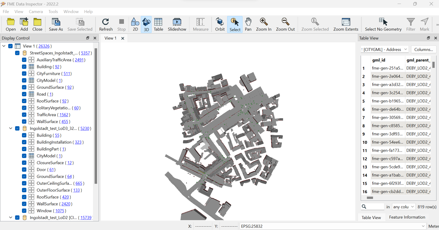
Make sure your view is set to 3D (if it is not already). Now use the ‘Orbit’ tool from the ribbon to tilt the model.
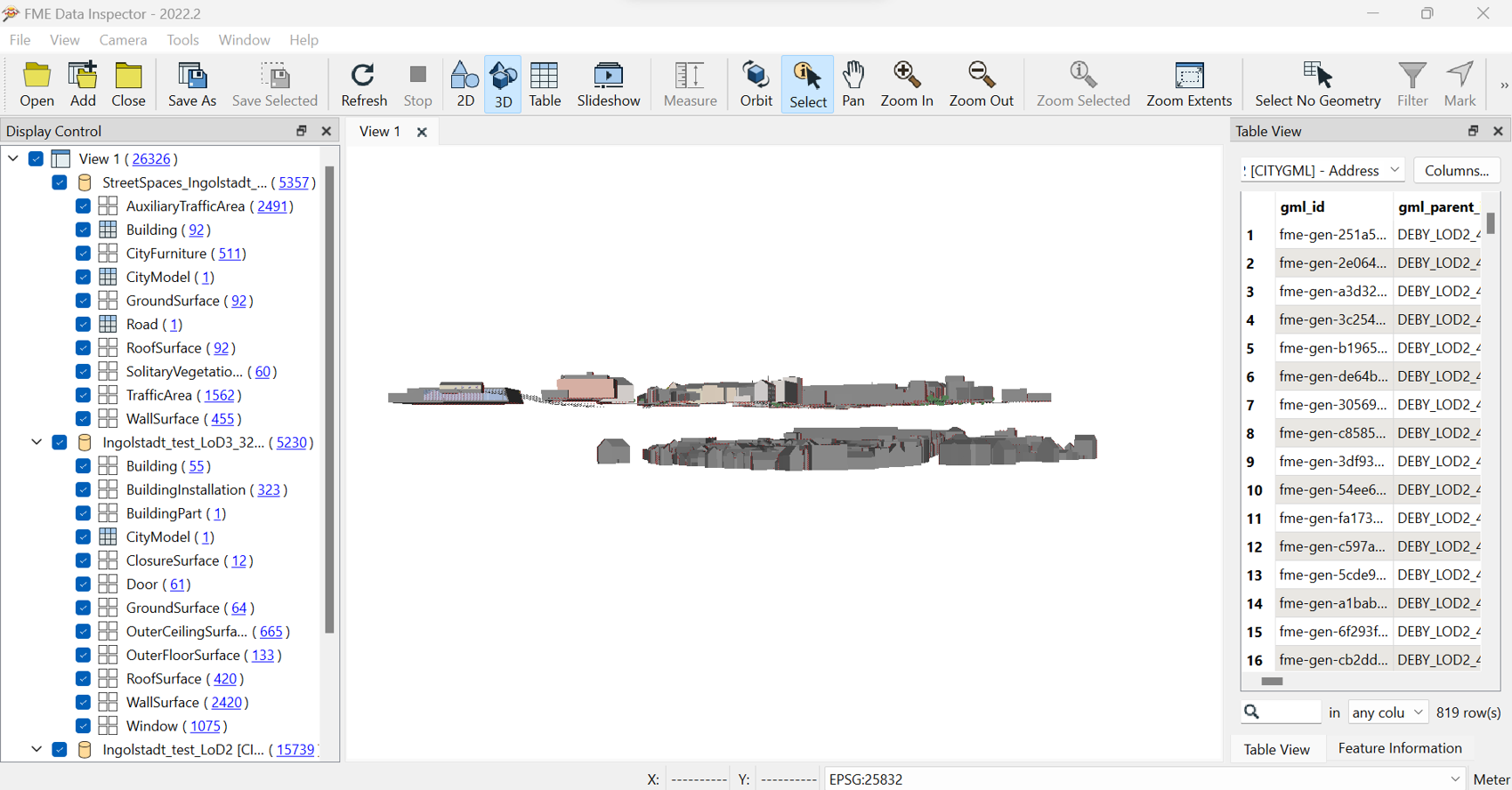
The models are not aligned along their z-axis. You can use the toggle the datasets and identify which datasets do not align. This is due to the difference in the coordinate and height reference systems.
Note
You can click on the features and from the ‘Feature Information’ tab, you can check which coordinate system is in use by the dataset. In this case the LoD3 models and the Street Space models are in a different coordinate system - WGS84 UTM (EPSG:32632) - to the LoD2 models (EPSG:25832). If you remember from the lecture – the EPSG:25832 is a UTM coordinate system (ETRS 89 – UTM Zone 32) and this is the system which our final dataset will use.
Task 1 - Filter the LoD2 dataset by the buildings in the LoD3 dataset.
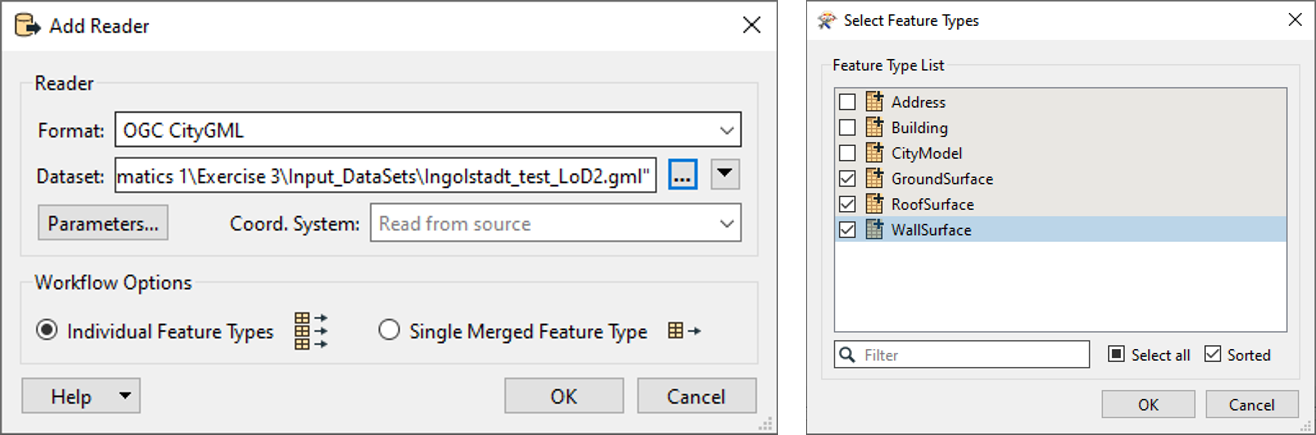
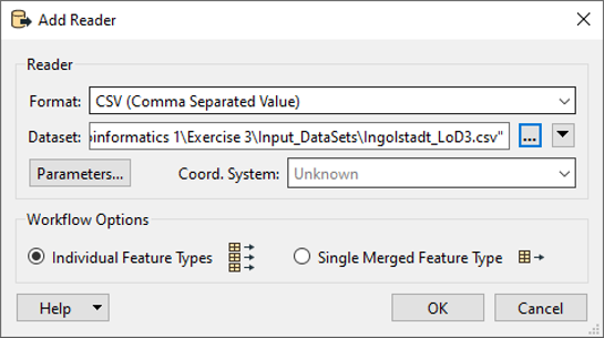
Open a fresh FME workbench and import your readers.
First import the LoD2 Dataset -> You can choose which layers to import. For this exercise, we are only dealing with the geometry of the building models and hence will only select the GroundSurface, RoofSurface and WallSurface.
Tip
If you look at the inspector, you will see that the Building layer also contains geometry. But this building layer is decomposed into surfaces due to the semantic organisation of the CityGML Dataset and would be a repetitive geometry. It is not required in this case, as the final output is a simple visualisation and does not require the semantic structure from CityGML.
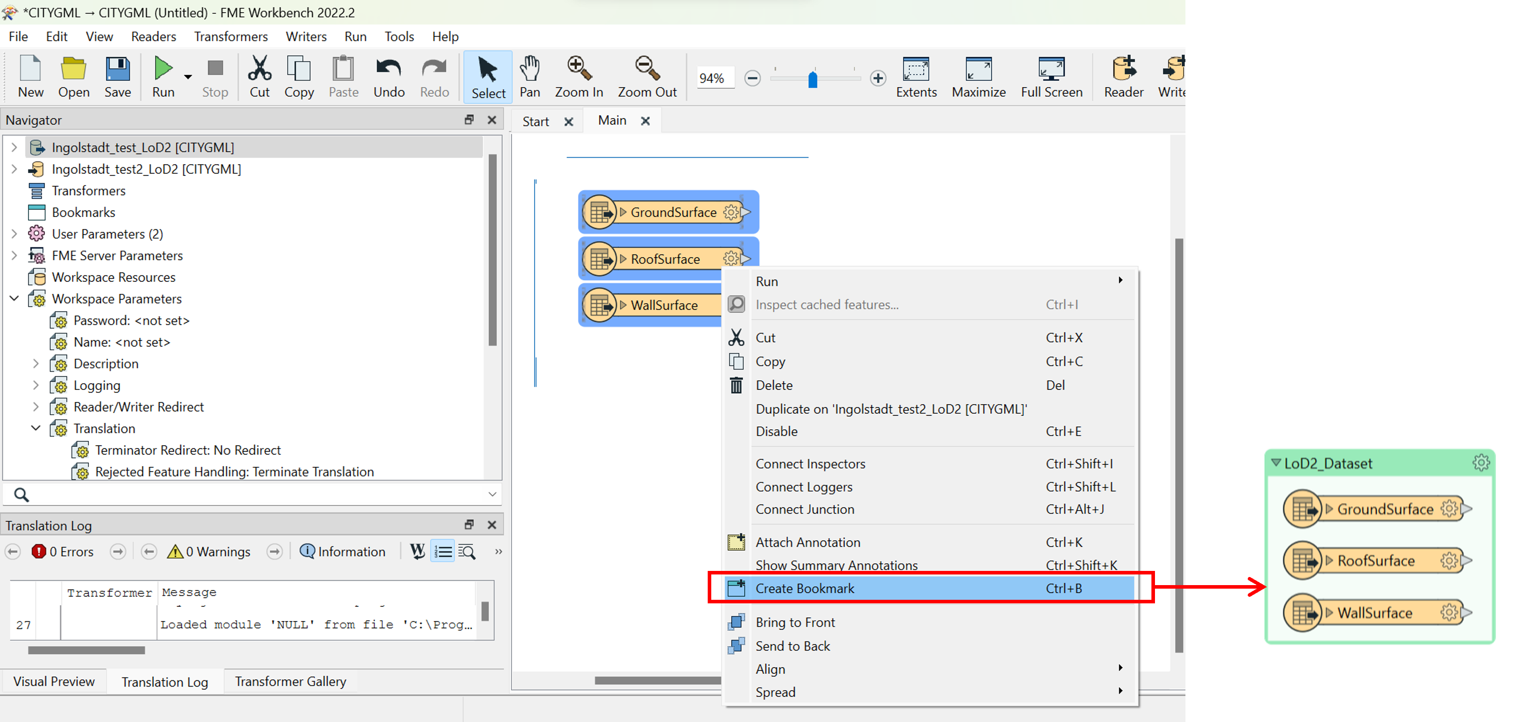
You can additionally select your readers, right click, and choose ‘Create a Bookmark’ to group them into a single block to organise your workbench for clarity and efficiency.
Import the csv dataset consisting of the names and IDs of the LoD3 models. This is used to filter out the LoD2 models that have the same ID as the LoD3 models and in the next step, we will replace the filtered data with the LoD3 geometry.
Note
In this dataset - The LoD3 models have been developed with LoD2 models as the basis and hence have the same IDs as the LoD2 models. This might not always be the case and should not be assumed.
After adding the csv file, add the Transformer – ‘FeatureMerger’. This is used to filter out the LoD2 model (Requestor) with the IDs from the CSV file (Supplier).
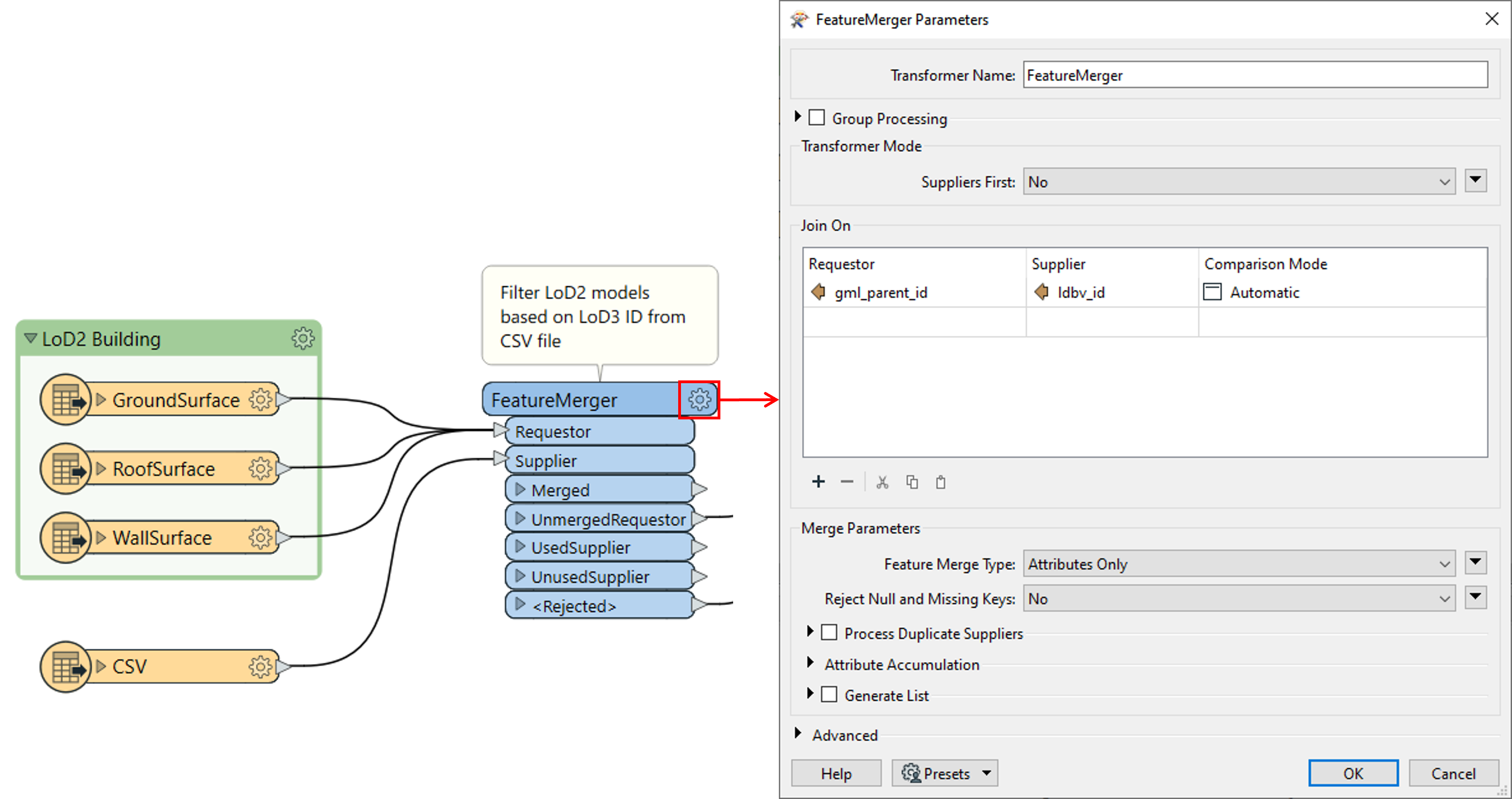
Click the settings gear on the transformer and set the parameters of the FeatureMerger as shown in the screenshot. This will define the comparable parameters to check between both the datasets.
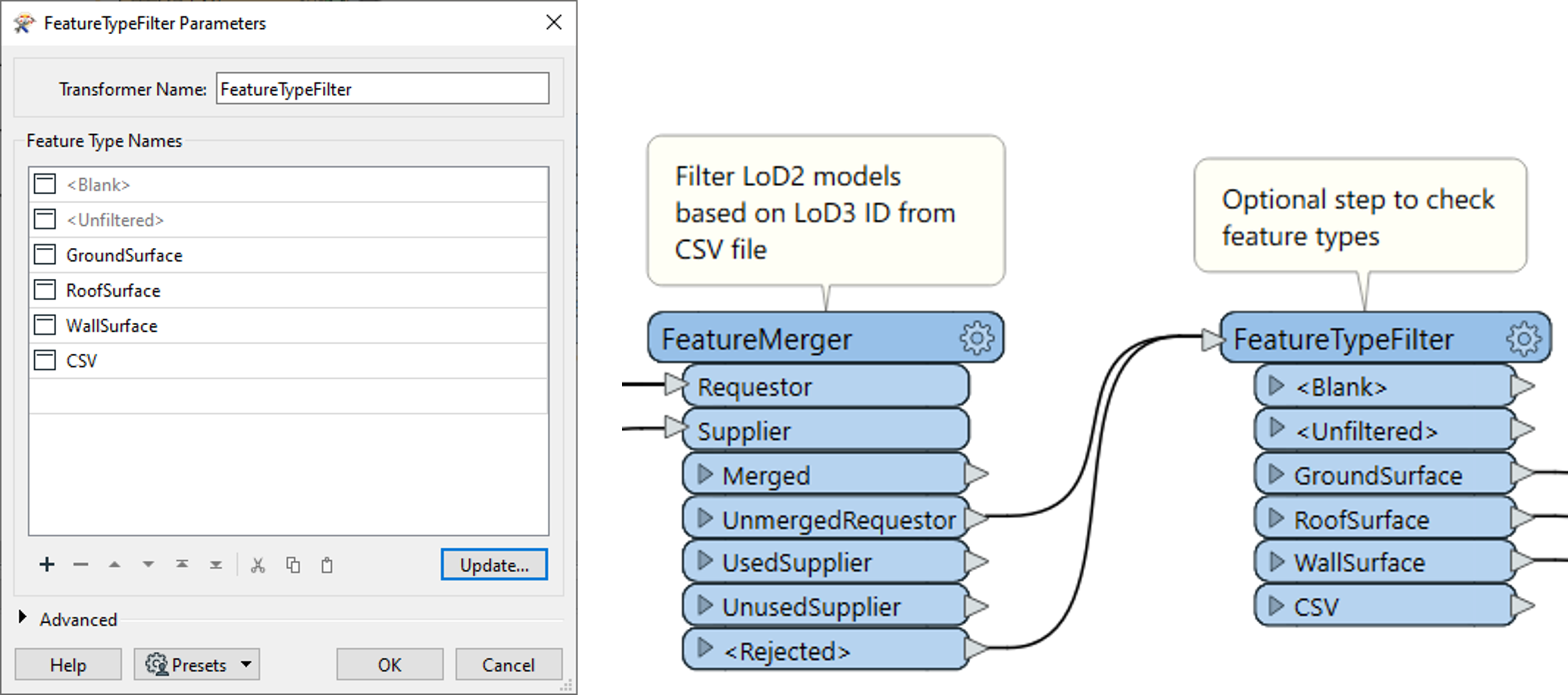
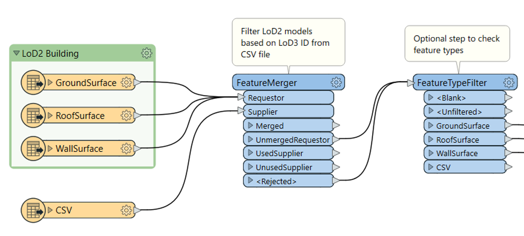
OPTIONAL: Add the next transformer – FeatureTypeFilter and ‘Update’ its parameters as shown. This is used to separate all the features of the input dataset.
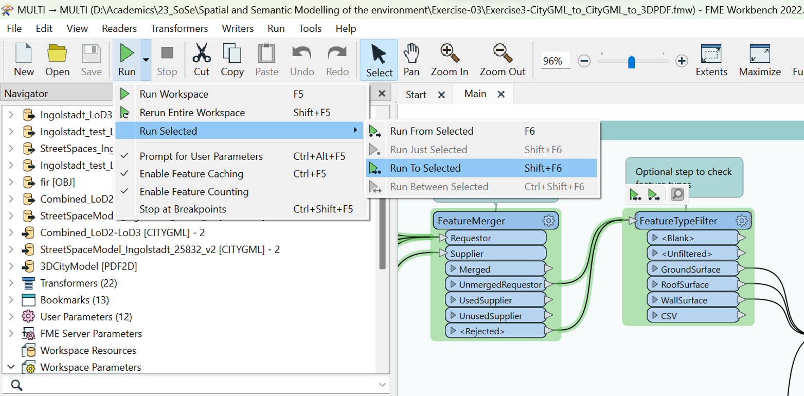
You can run this process using the ‘Run to Selected’ option from the drop-down menu of the Run Command in the tools ribbon to check if everything is working. You can view the result in the ‘Visual Preview’ at the bottom of the page.
Import the required layers of the LoD3 building geometries – BuildingInstallations, Door, GroundSurface, RoofSurface, WallSurface, Window, and bookmark them.

Note
Since they are in a different coordinate system and consist of a vertical offset, we need to reproject and align them using the Reprojector and Offseter transformers. The parameters of each of the transformers can be defined as shown below.
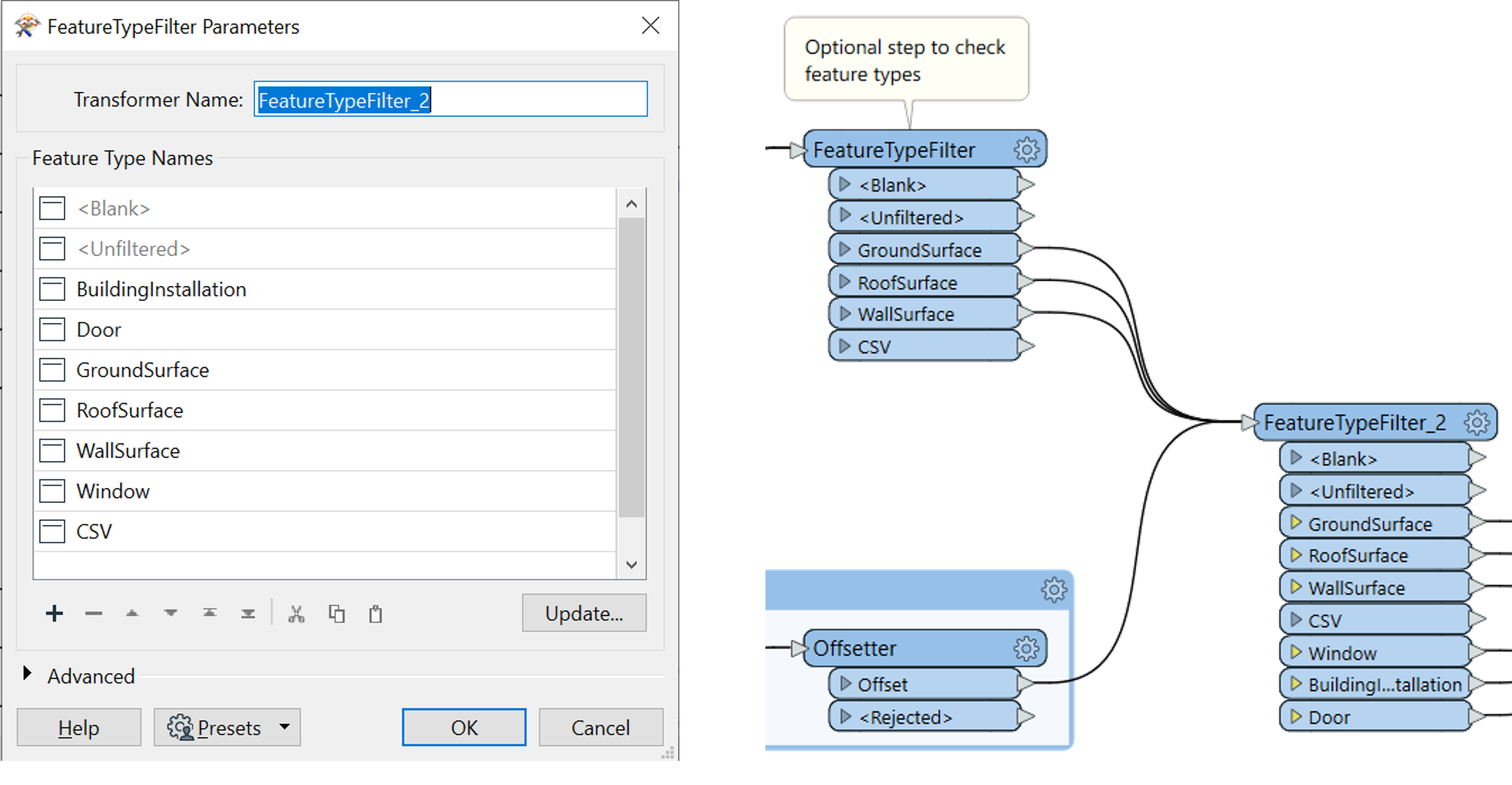
Next add the transformer – FeatureTypeFilter and click ‘Update’ to identify all the features of the LoD2 and the LoD3 models.
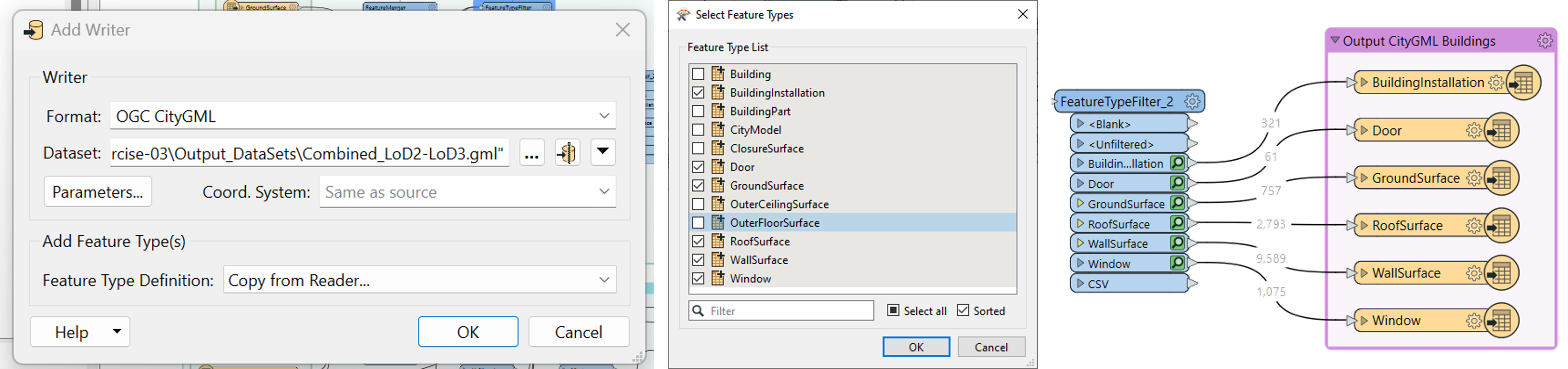
Now add a CitGML Writer to the workbench. Choose the ‘Copy from Reader’ option and choose the layers that exist in the FeatureTypeFilter_2.
Note
There might be multiple features with the same name if there are multiple readers. Do not worry, you can choose just one feature from either of the datasets.
Once the write is added, connect the corresponding features.
This is the overall process for Task A.
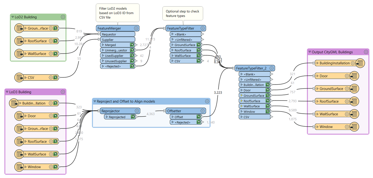
You can now visualise the final combined model in FME Data Inspector and check if everything is correct.
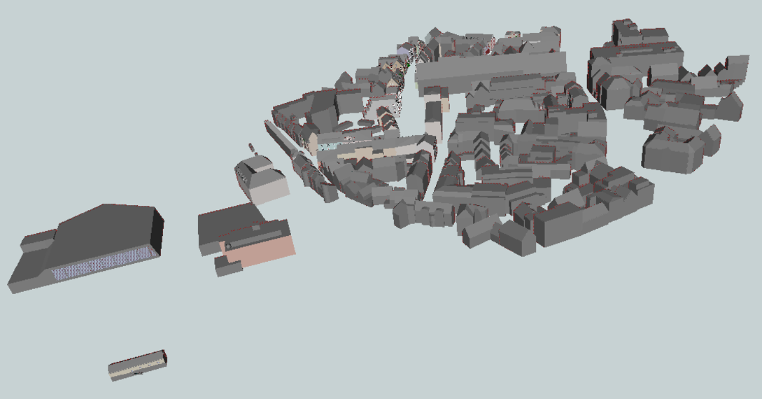
Task 2 - Add streetspaces to the result of Task 1 and substitute placeholders with trees
To the same workbench, import another CityGML reader. Select the StreetSpace model.
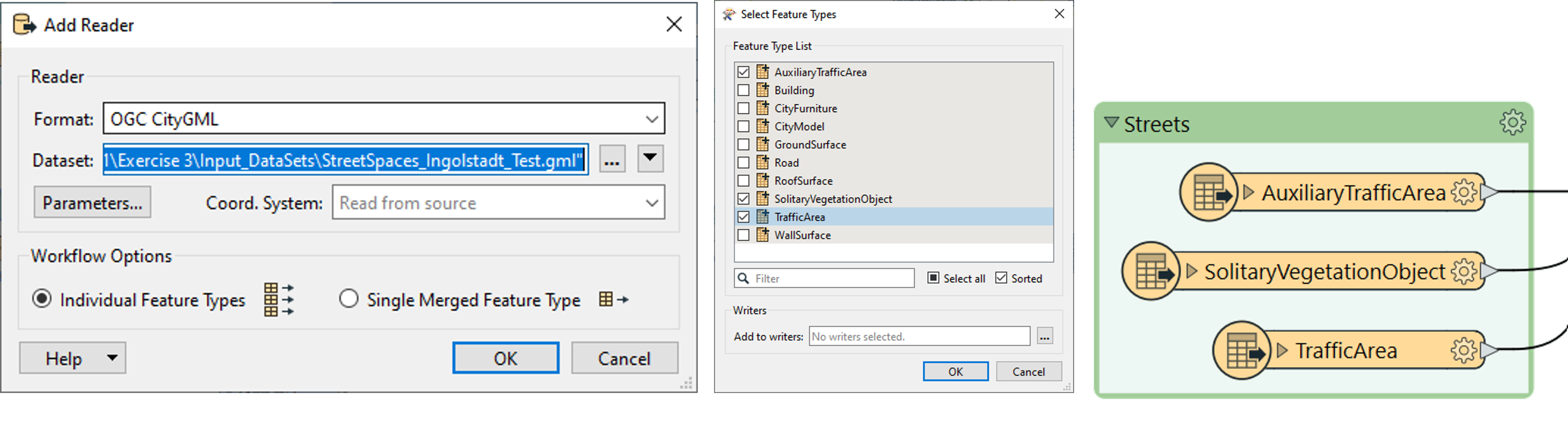
Note
In the Data Inspector, you will see that only a few layers have Geometry information in this dataset. Choose only the layers with geometry and import the dataset. Since this dataset is also in a different coordinate system, reproject and offset it as in the previous task.
Tip
You can copy and paste the transformers to preserve the parameter settings.
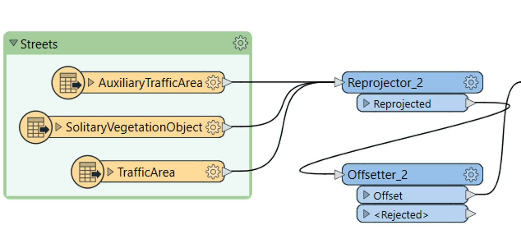
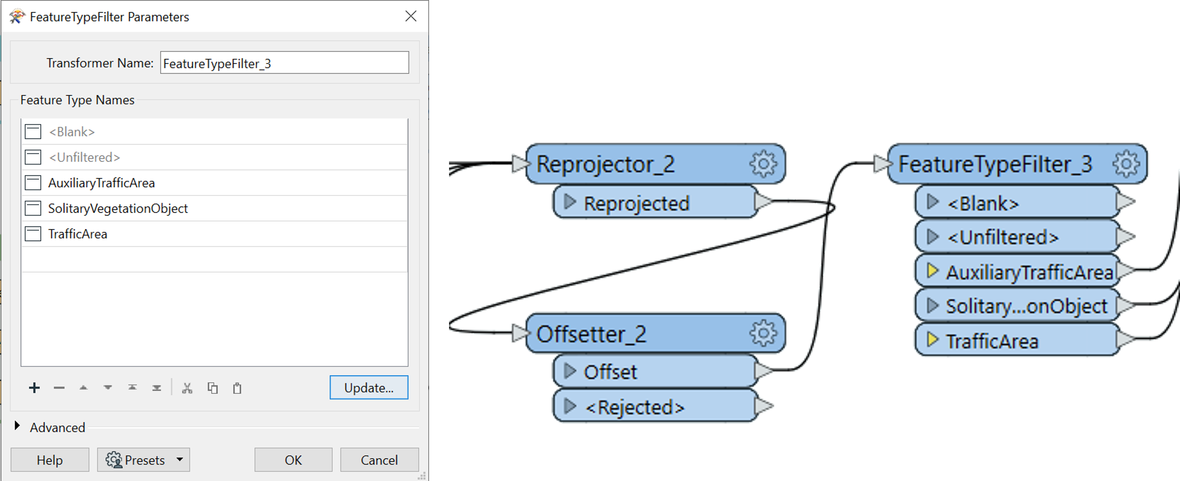
Add a FeatureTypeFilter to separate the features after reprojection and offset.
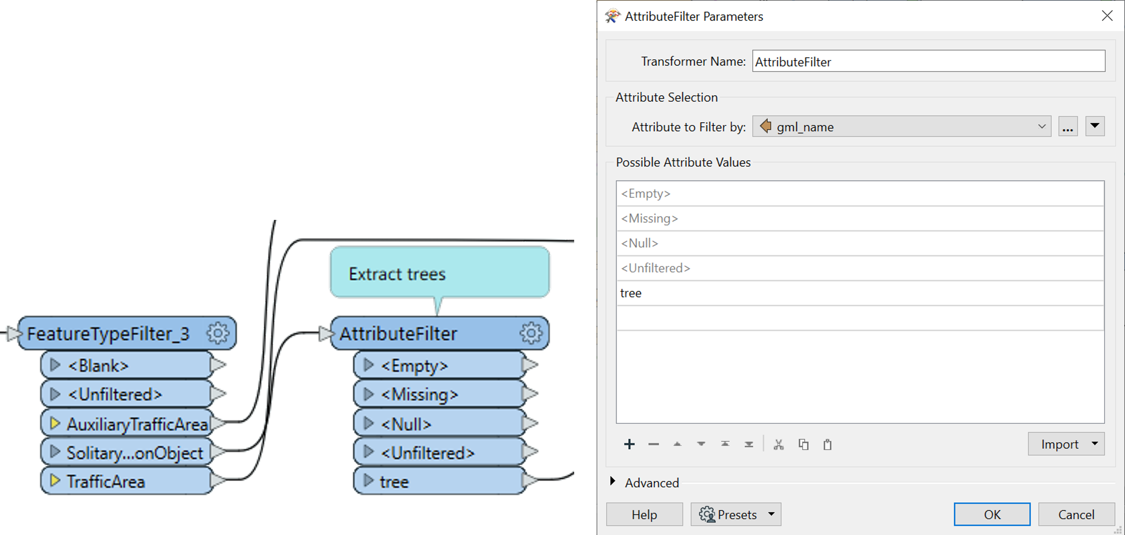
Next use an AttributeFilter to identify ‘trees’ from the layer SolitaryVegetationObject
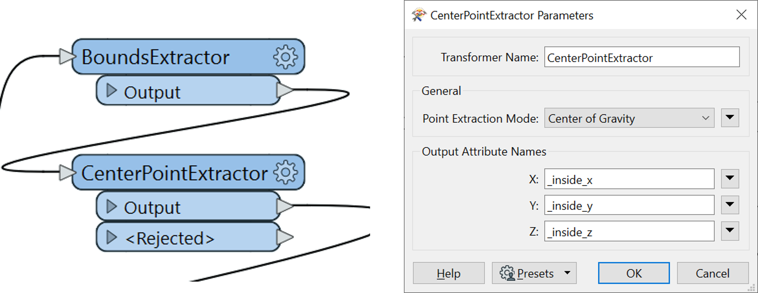
Next, we need the BoundsExtractor and the CentrePointExtractor to get the x, y, and z coordinates of the trees. There is no change in the parameters of the BoundsExtractor as it is only used to extract the z_min of the object.
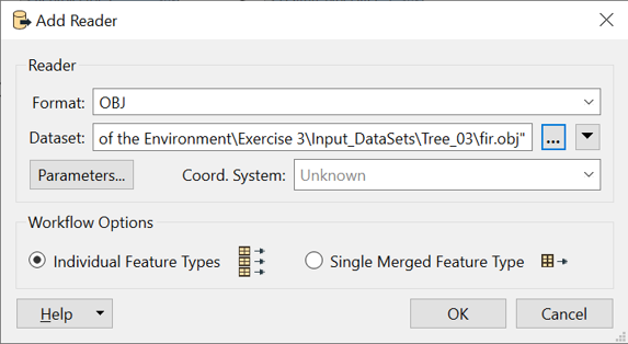
Import the 3D Tree model dataset using the appropriate reader (.obj, .dae, etc., as per the model type). Here the example is shown with an OBJ model.
Tip
You can also download a freely available tree model from the internet in any format. Make sure it is a Low-Poly model to optimize runtime and increase efficiency of the workbench.
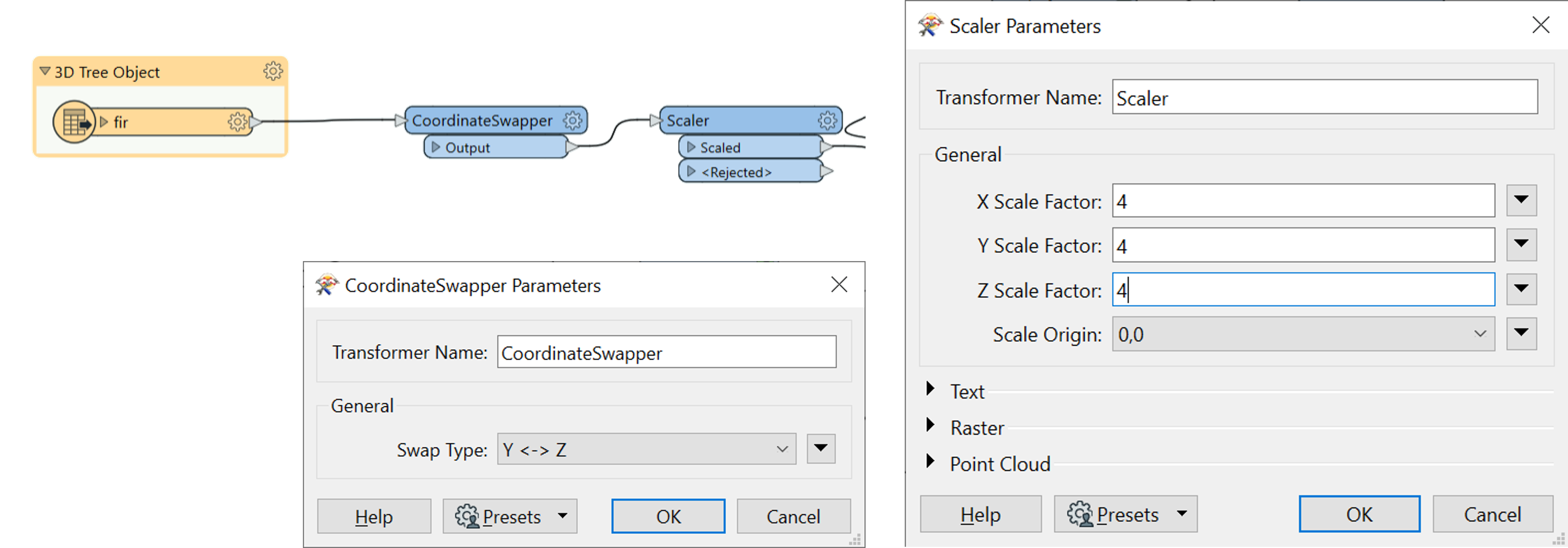
To this reader, attach a CoordinateSwapper and a Scaler to orient and adjust the models to the right position and scale in the City model.
To this, add a FeatureMerger to merge the scaled 3D Tree models with the placeholder geometries in the StreetSpace model.
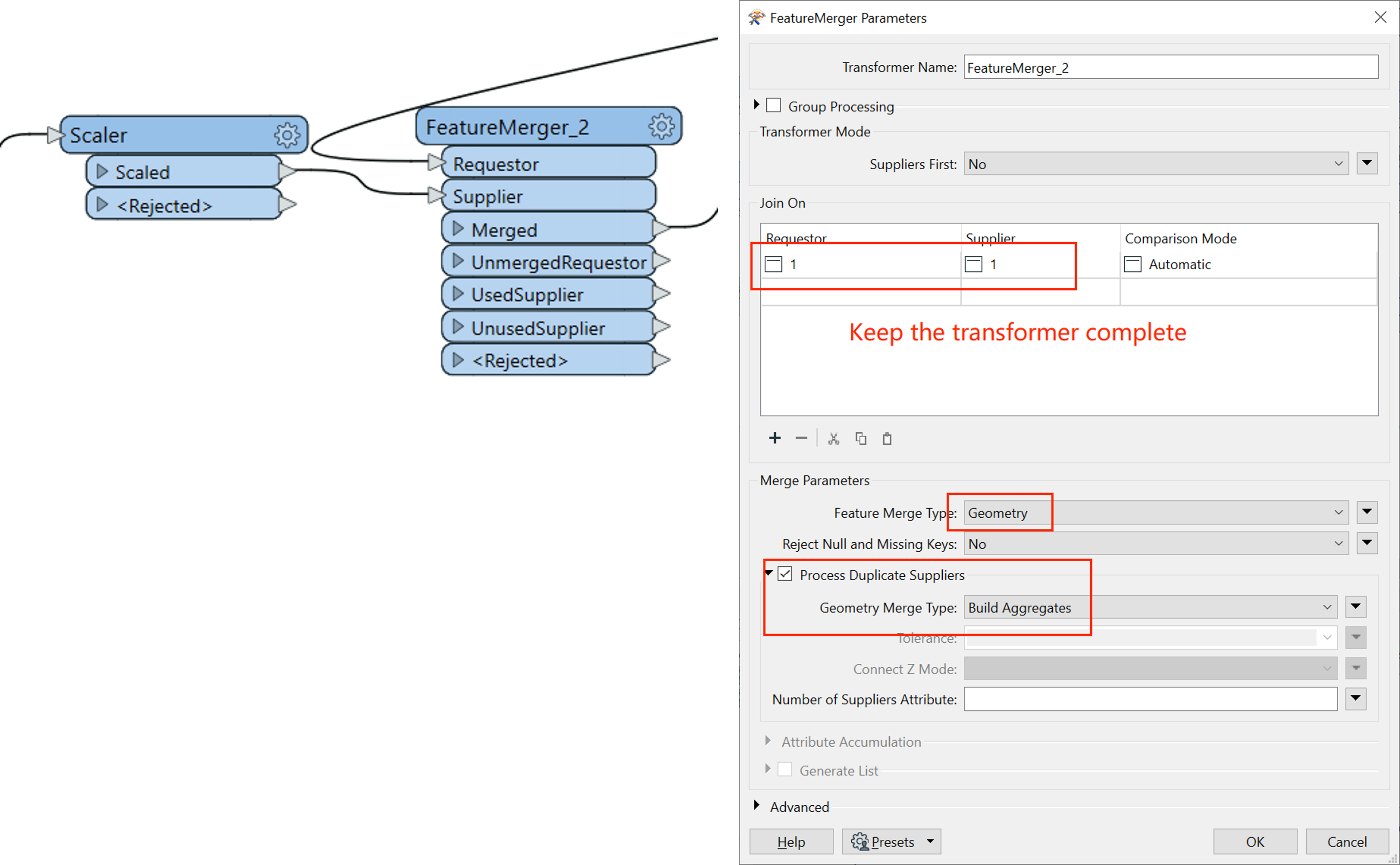
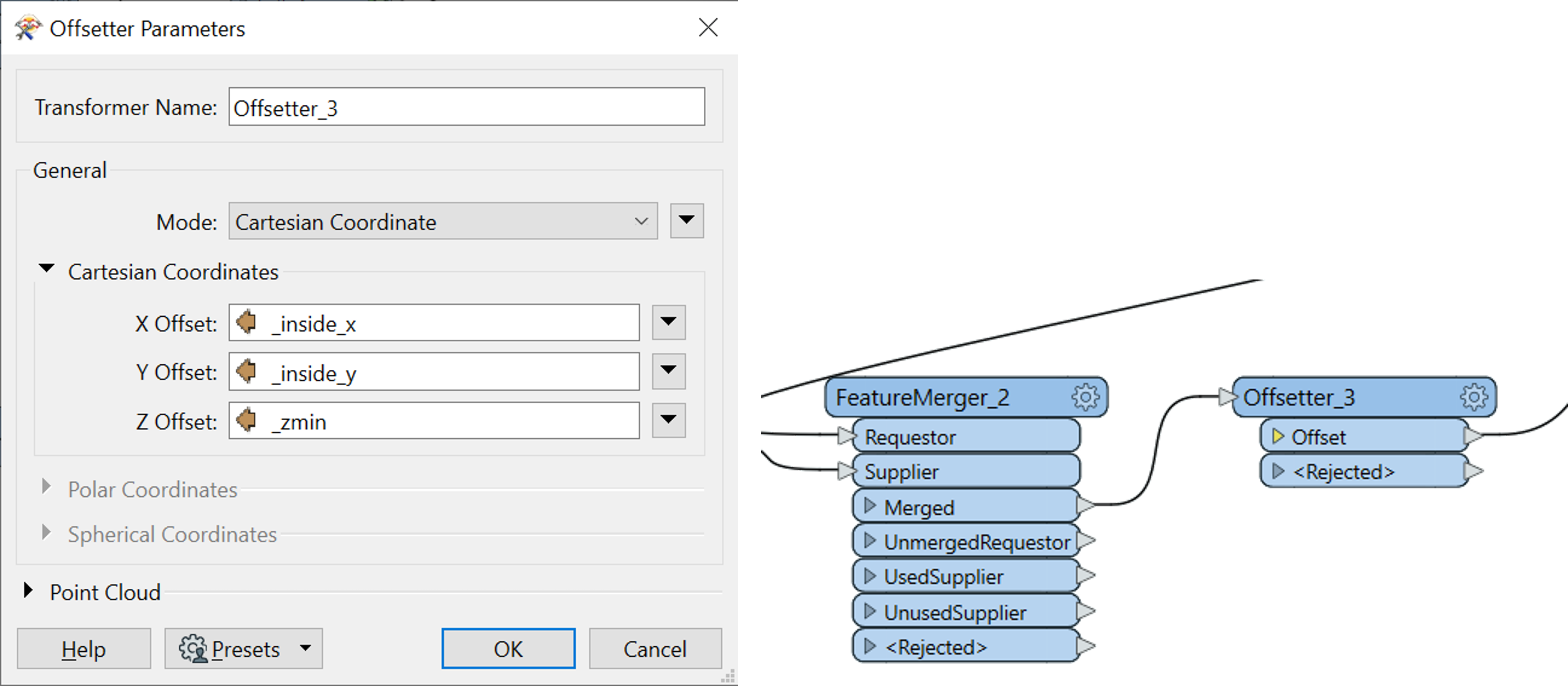
An Offsetter is added to this to position the tree as per the coordinates defined by the offset, since the 3D tree model does not have geographic coordinates.
Now add a CityGML writer to store the street space model with the substituted trees.
Tip
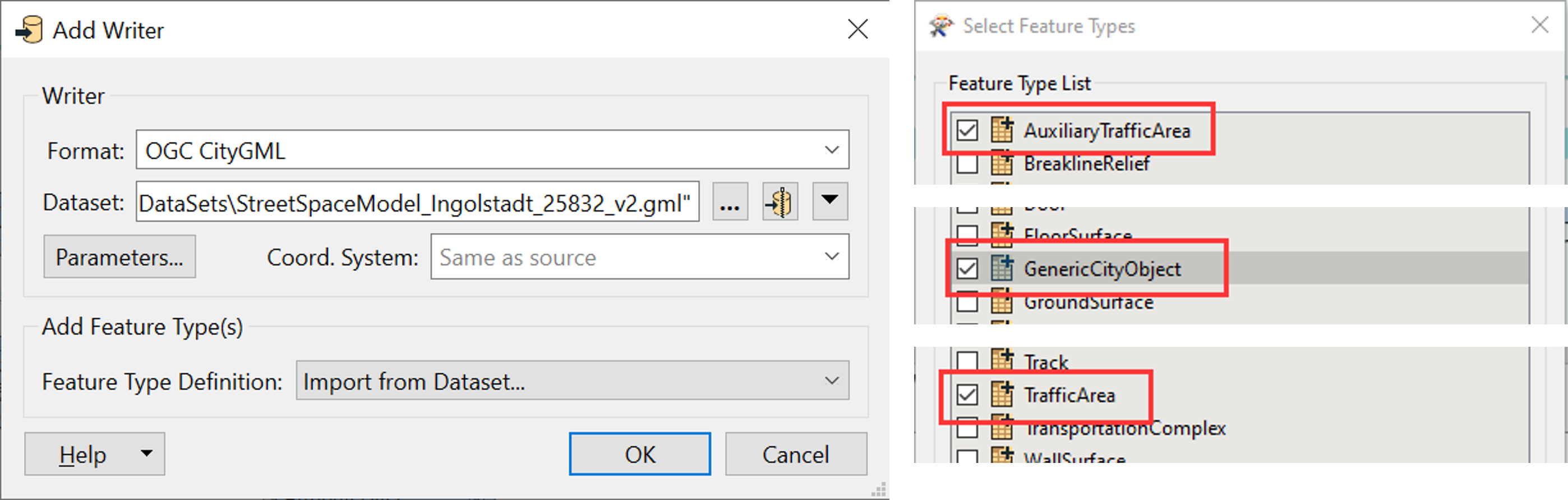
For ‘Feature Type Definition’, Select feature types from the default FME Directory in your Program Files. Go into C:>Program Files> FME> xml> CityGML> writer_feature_types> CityGML_feature_types.xml and choose Choose only the corresponding feature types from the list. Trees are stored as GenericCityObject, since a new object type is added into the model.
OPTIONAL: Additionally, you can change the name of the CityGenericObject writer to either SolitaryVegetationObject or Trees for clarity if you prefer. Next, connect the final offset trees with the SolitaryVegetationObject in the writer. For the others – TrafficSpace & AuxiliaryTrafficSpace – Connect from the FeatureTypeFilter_5, used after the reprojector and offsetter.
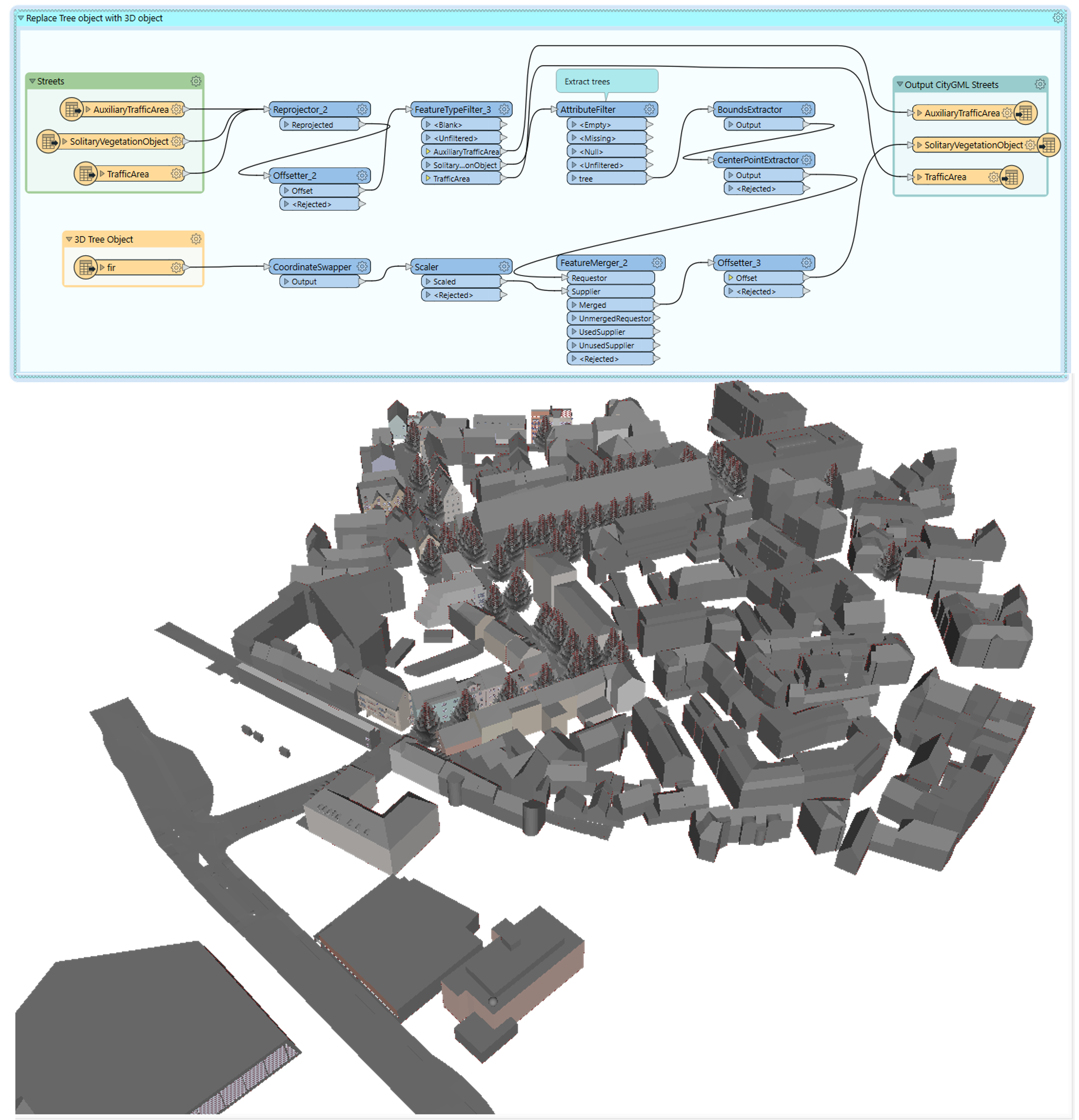
The final workflow for this task looks like this. You can now visualize this output in FME Data Inspector along with the output of the first task to check if everything aligns.
Save the workbench, and the results from Tasks 1 & 2. These will be required for the following exercises.
Task 3 - Adding Appearance from Aerial Orthophotos
In this task, we’re going to further enrich the CityGML models by adding simple textures from high-resolution orthophotos as discussed in the previous lecture.
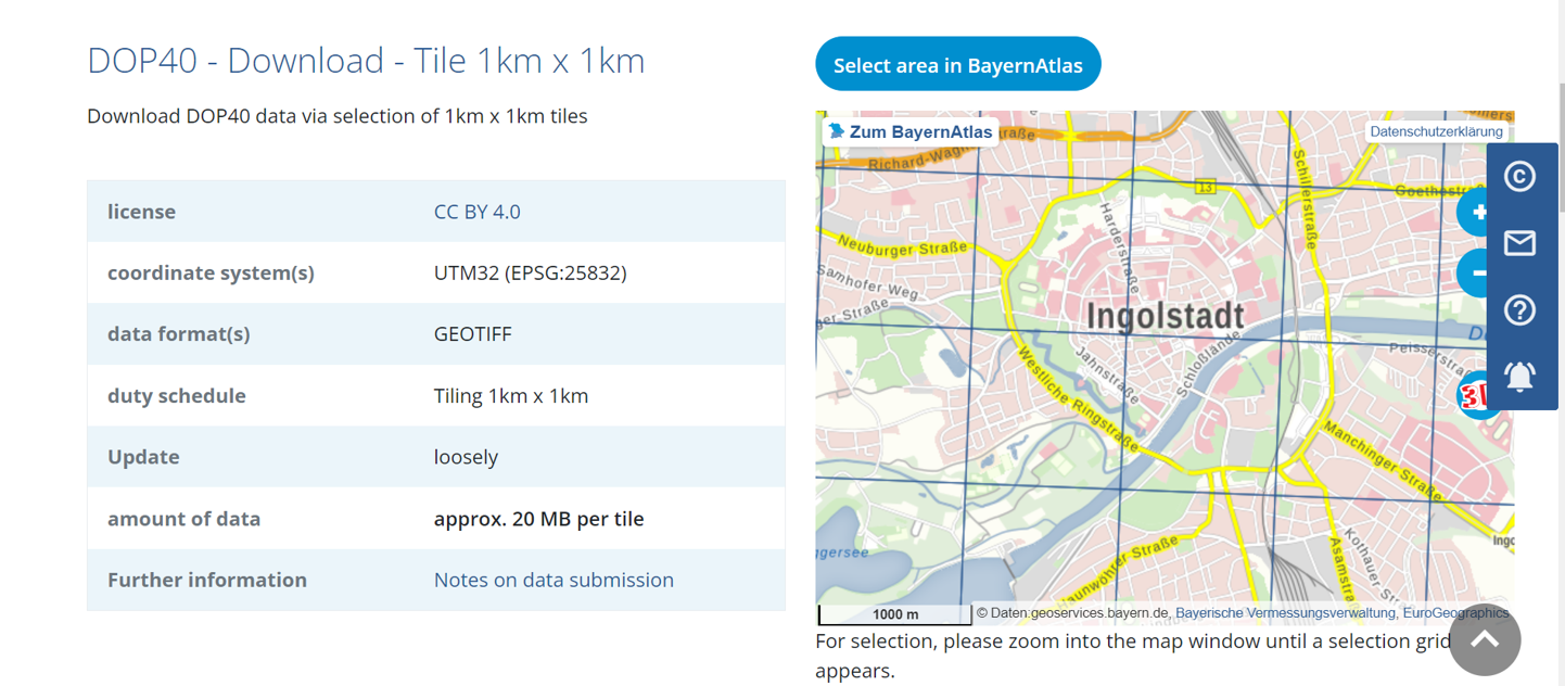
The orthophotos can be downloaded from the Bayern Open Data Portal.
Open your CityGML files created from Task 1. Check the extent of the dataset on the map (using FME 2D viewer) and download the corresponding image(s) from the portal by zooming into Ingolstadt area using the Bayern Atlas.
First import the CityGML and the GeoTIFF (Orthophotos) datasets to your workbench and bookmark them like you did in the previous tasks.
Note
The number of GeoTIFF readers depends on how many orthophotos you are importing into the workbench and that depends on how many are required for your dataset extent. Here the GeoTIFF used are - 32677_5403 and 32678_5403.
Use the RasterMosaicker transformer to combine the raster datasets and resample them. There is no need to change any of the default options in the transformer.
Now that the rasters are prepared, we must convert the relevant 3D geometries to 2D geometries to match the raster with the corresponding geometry. For this, use the 2DForcer transformer to convert the 3D RoofSurface, TrafficArea, AuxiliaryTrafficArea into 2D.
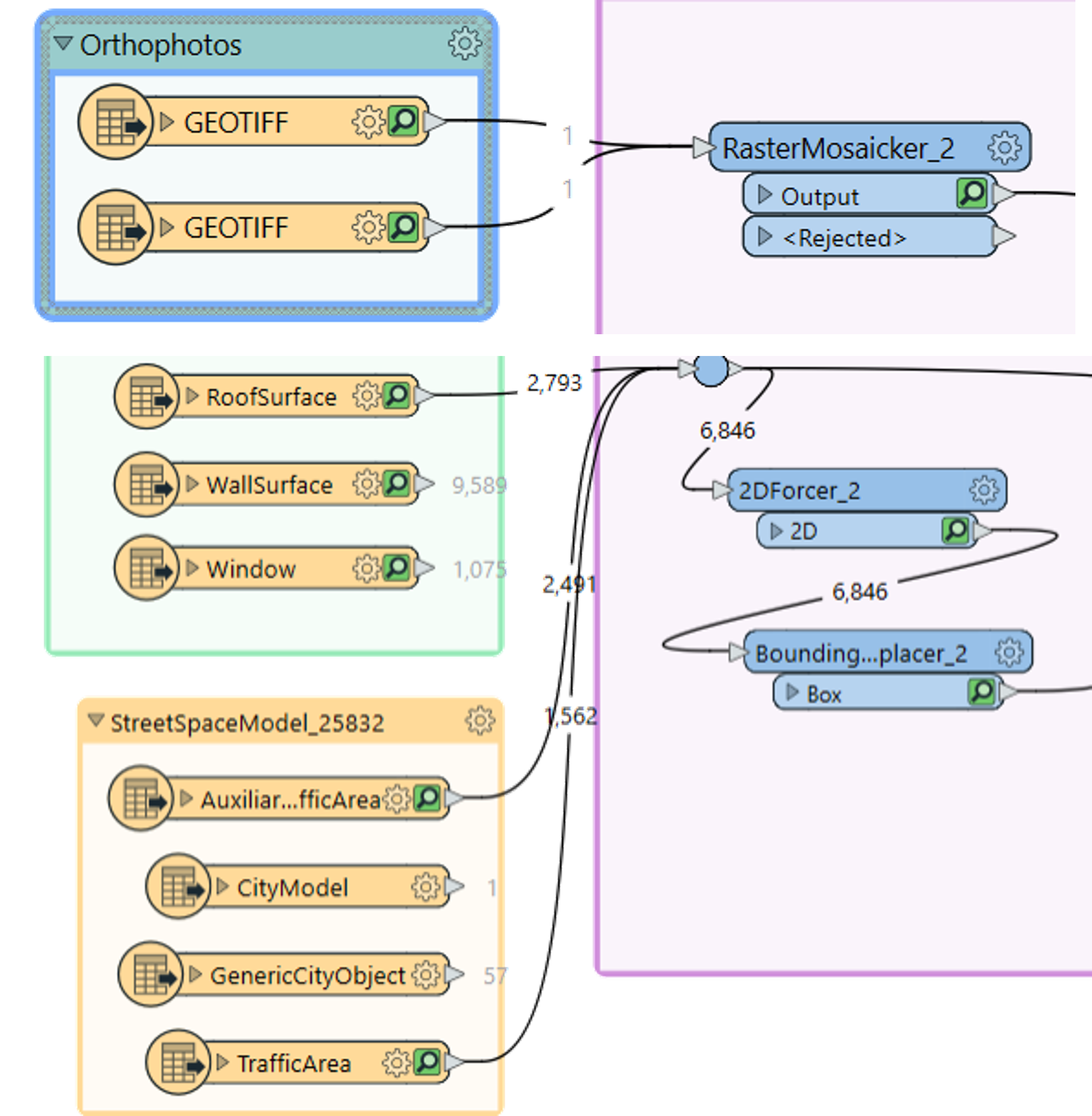
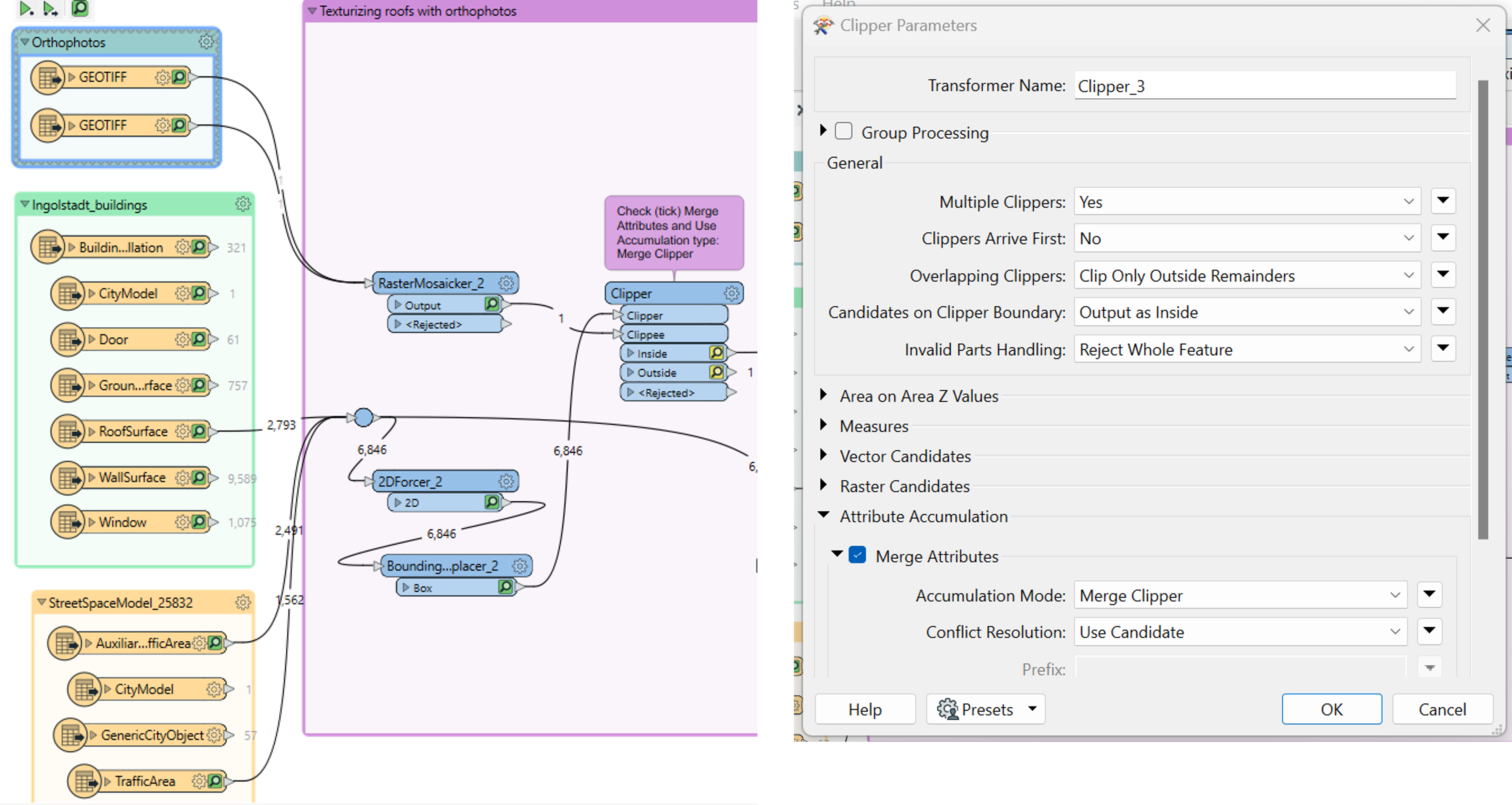
Further, use the BoundingBoxReplacer to generate the bounding boxes of the forced 2D geometries for clipping using the Clipper transformer. In the transformer, open the parameters and select ‘Merge Attributes’
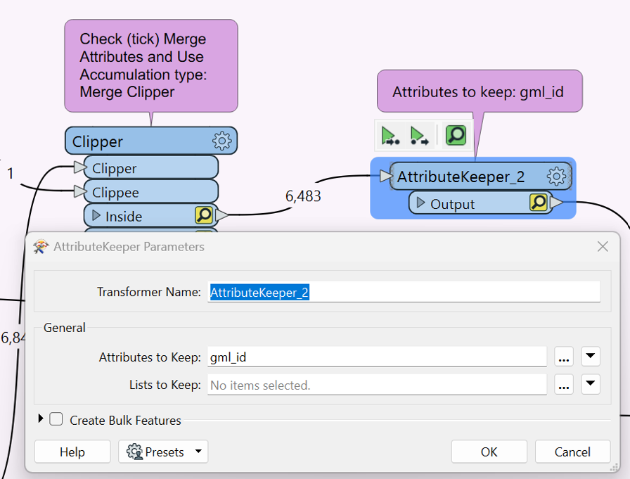
Then, connect the ‘Inside’ output of the Clipper transformer to the AttributeKeeper and open the parameters. In this select ‘gml_id’ as the attribute to keep.
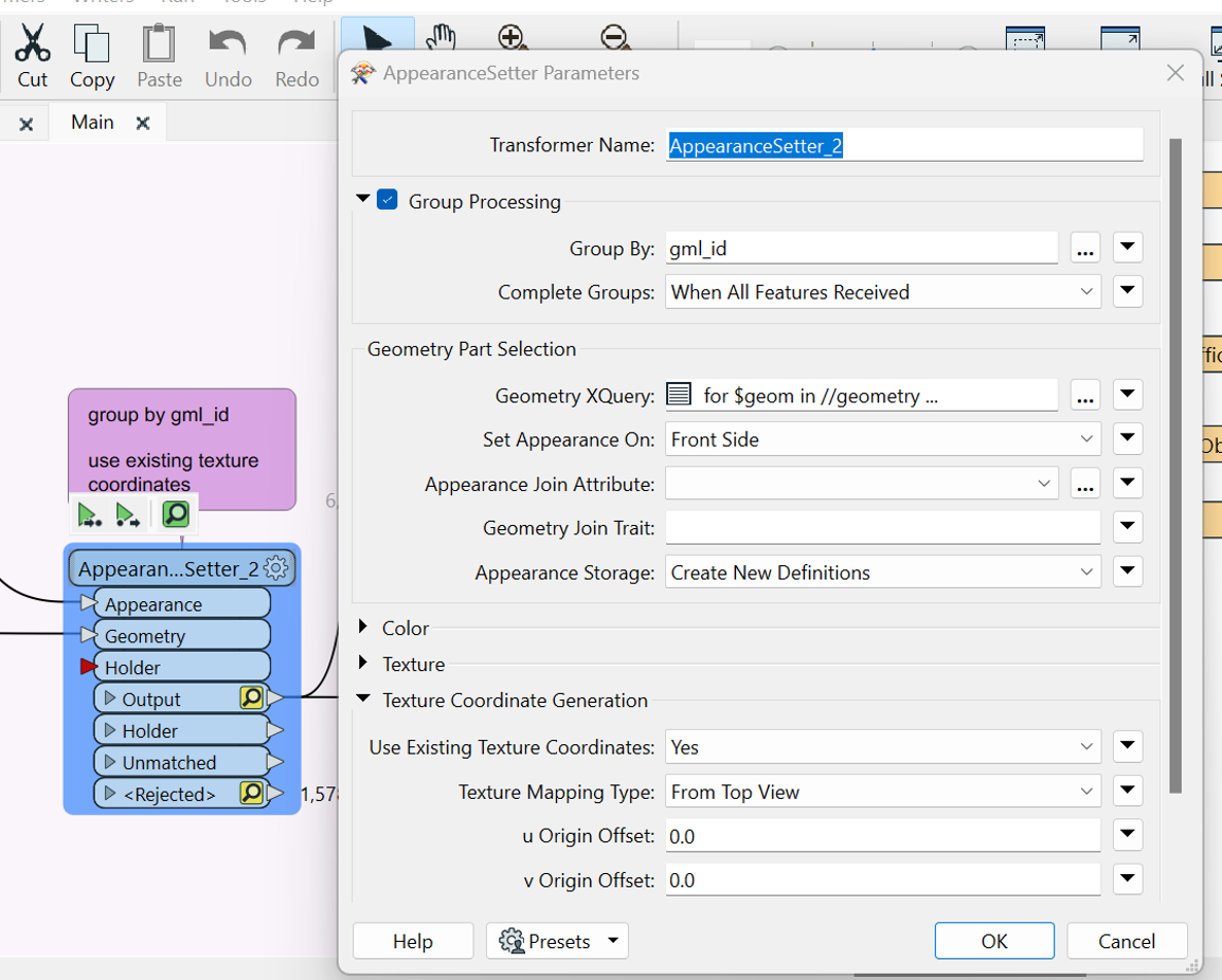
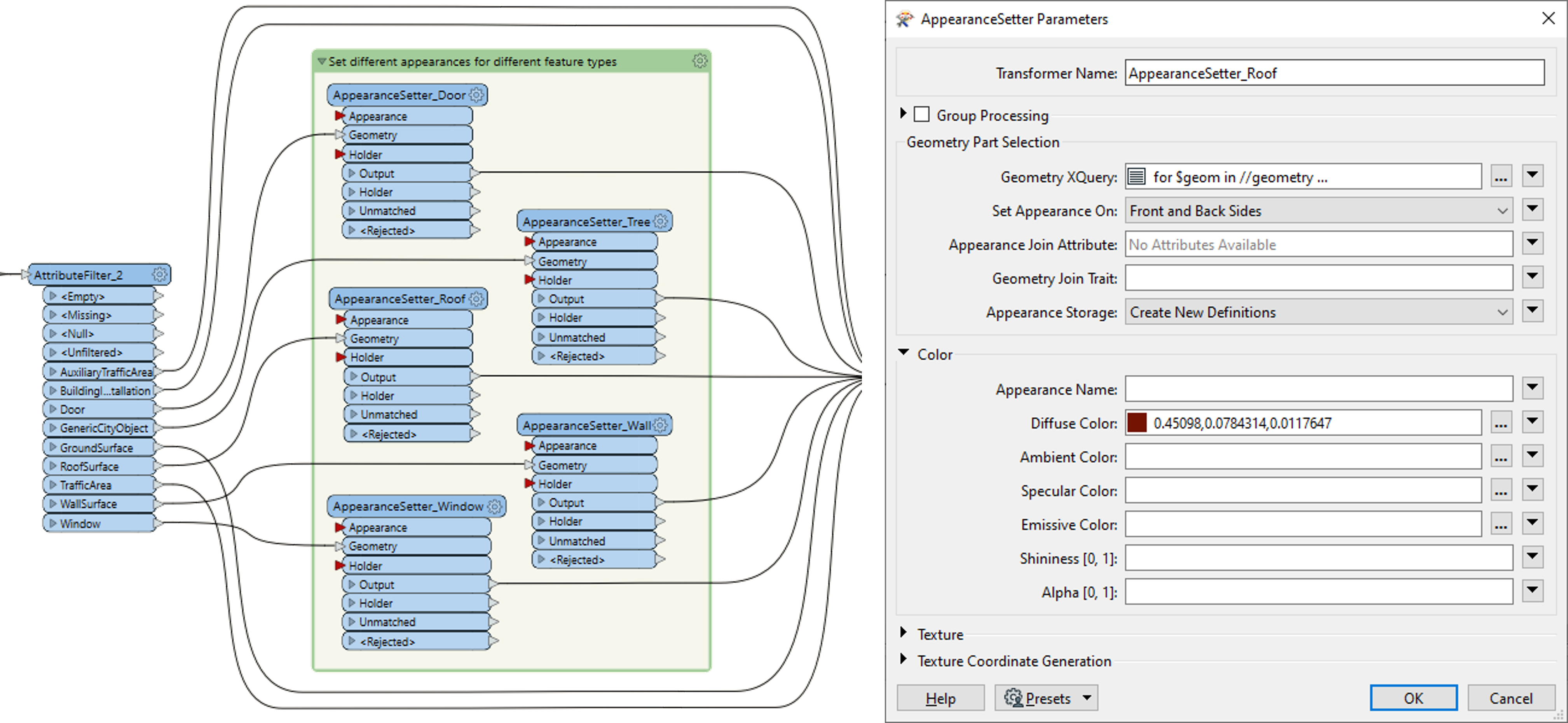
Next, use the AppearanceSetter transformer to match the raster clippings to their corresponding 3D geometries. The ‘Appearance’ is from the Clipper while the geometries are taken from the original CityGML reader layers. Input geometries from RoofSurface, AuxiliaryTrafficSpace, and TrafficSpace.
In the AppearanceSetter parameters, Group By: ‘gml_id’ and in the ‘Texture Coordinate Generation’, select ‘Use Existing Texture Coordinates’ as Yes and ‘Texture Mapping Type’ as From Top View
Note
A similar approach can be followed for adding textures to WallSurfaces or any other building components if you have high-resolution images but it is not as straight forward. You would need to develop a method to match the Surfaces with their corresponding images, making sure the normal aligns and then add textures.
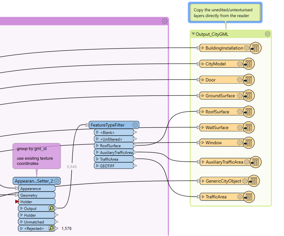
Once the images have been attached to their corresponding geometries, you can use the ‘Inspector’ to check the quality of your output. Then use the FeatureTypeFilter to filter out the layers and then connect them to a ‘CityGML’ writer and create your output .gml file as you did in Tasks 1 and 2.
Tip
Connect the other components (WallSurface, GroundSurface, Windows, Door, BuildingInstallations, Trees) from the reader to the writer directly and run your workbench.
Once the translation is successful, open the folder where your output is stored. You will see the .gml file along with an additional folder with the same name where the textures are stored.
Tip
Always make sure the texture folder and the gml file are stored in the same place.
Open your output file in the Data Inspector and analyse it. The textures should now be added to the selected geometries.
Task 4 - Set Appearance and export as Adobe 3DPDF
Start in the same workbench from the last exercise if you wish or import the final data written at the end of Tasks 1 & 2.
Add the CityGML files generated as output for the previous 2 tasks as two separate Readers. This time we add additional parameters to the reader settings.
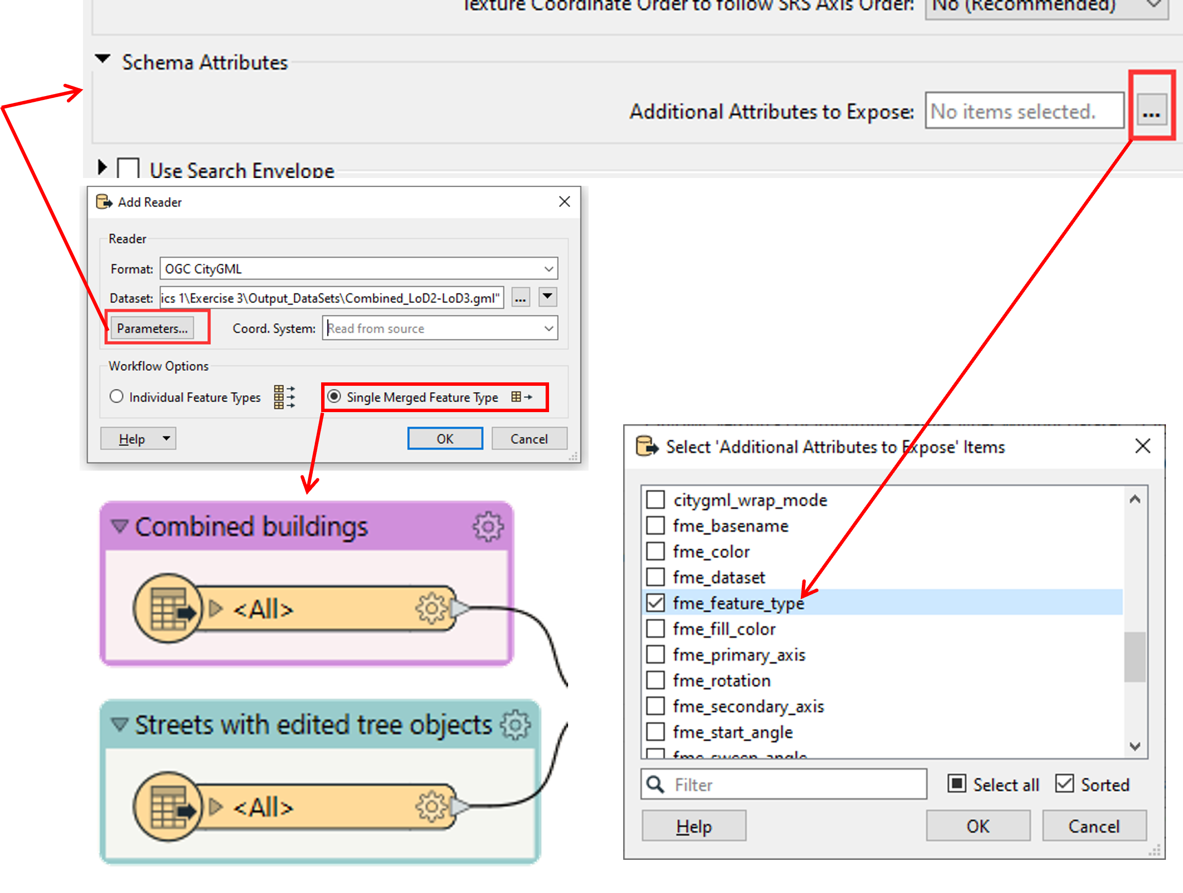
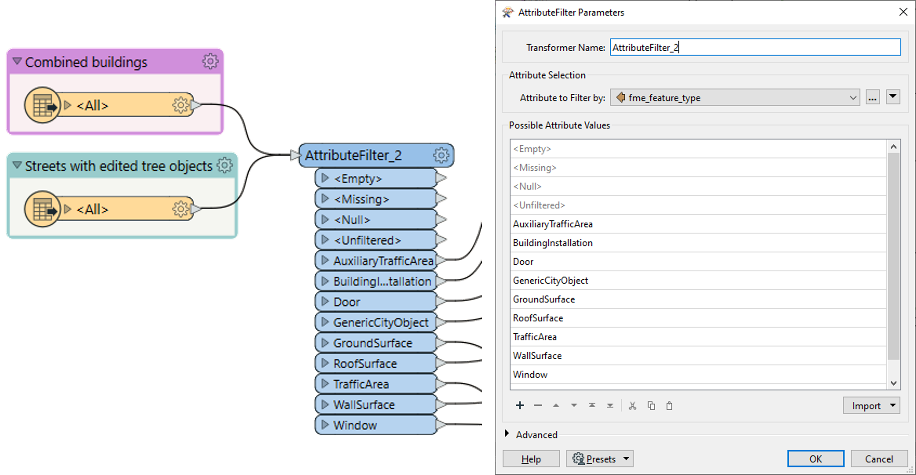
Use the AttributeFilter to identify features based on the exposed feature attribute
Next, use the AppearanceSetter to assign a colour to each feature in the CityGML readers. Repeat the process for all prominent feature types.
Use the AttributeCopier transformer to copy the attributes from the CityGML file to the 3DPDF
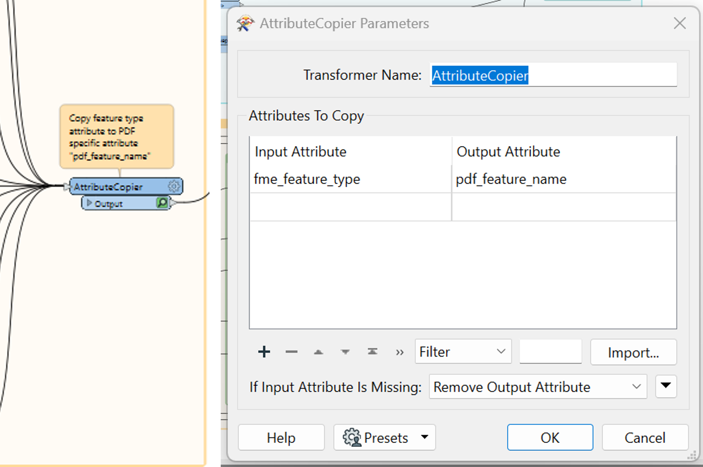
Tip
The attribute names can be found in the drop-down list of the input and output attributes when you click on it.
Export the model to a 3DPDF using the writer ‘Adobe 3D PDF’
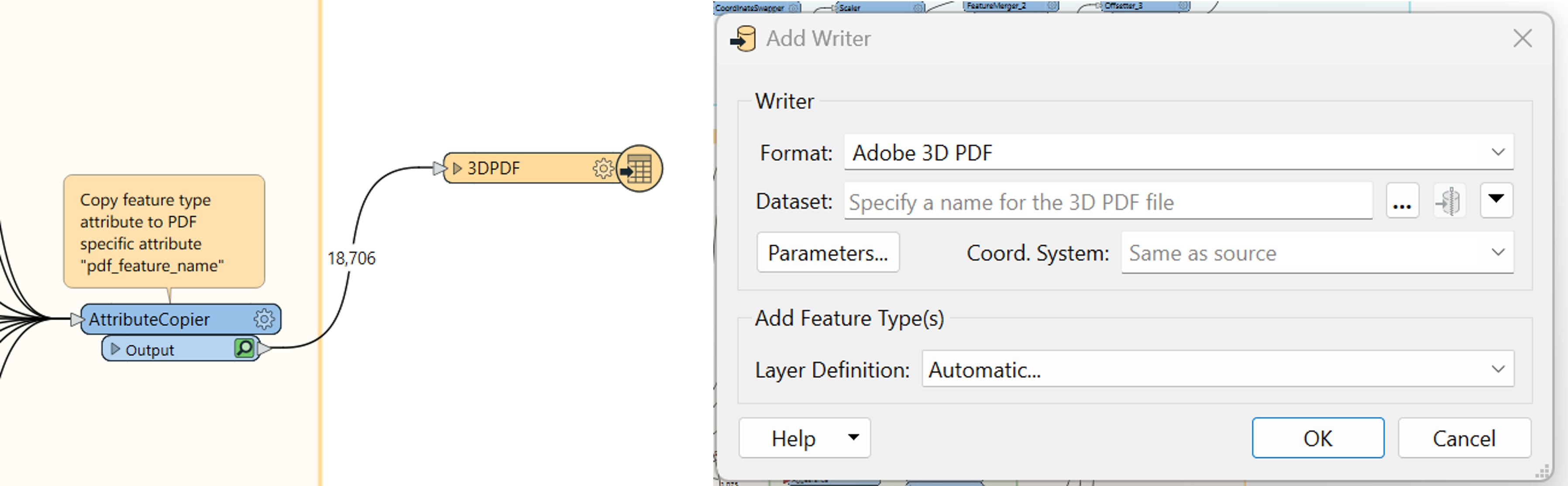
Tip
Use the Layer Definition – Automatic and specify the location and name of your output file.
The output should be visualised in Adobe Acrobat Reader and should look something like the following image.
Tip
In Adobe Acrobat Reader, you need to choose “Trust this Document” from the options before you can view the model
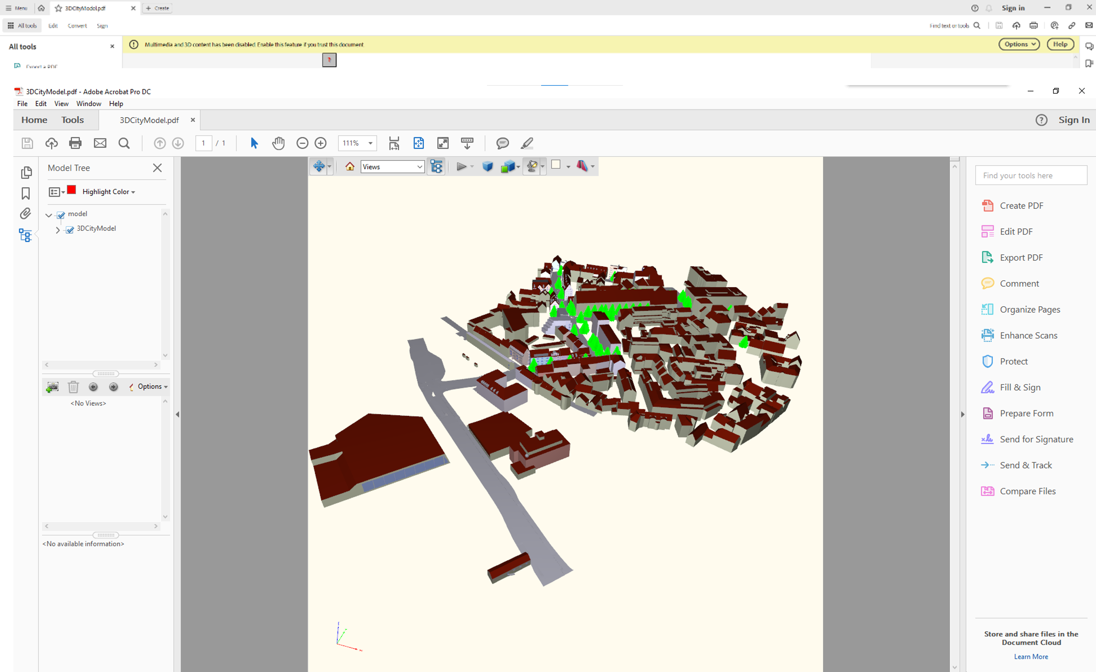
Note
While the FME workbench has a writer called ‘Adobe 3D PDF’, you will see that the Data Inspector does not give you the option to choose ‘Adobe 3D PDF’ when opening the file with FME. Hence, the file (as of now) can only be viewed in Acrobat Reader. The option ‘Geospatial PDF’ is very specific to 2D Data only and cannot handle 3D Geometry.
Task 5: Analysis of the SurfaceArea-to-Volume Ratio [OPTIONAL]
FME provides a variety of tools that can be leveraged to conduct diverse spatial analyses. In this task, you will calculate the SurfaceArea-to-Volume ratio of an LoD3 Building as a measure of compactness. Such a metric can be useful e.g. in estimating the energy demand of a certain building. The A/V-Ratio is calculated by dividing the overall suface area of a building by its overall volume.
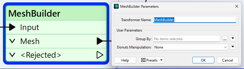
As a first step, you need to convert the relevant parts of the CityGML model into a mesh. In this particular case, all surfaces enclosing the Building must be considered and converted into a mesh using the MeshBuilder transformer:
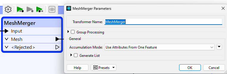
You can merge the resulting individual meshes using the MeshMerger transformer:
From now, the workspace is going to split into two branches: the calculation of the volume and the calculation of the surface area.
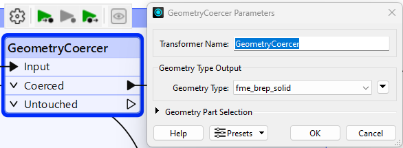
To calculate the volume with the VolumeCalculator transformer, you first need to convert the mesh geometry into a solid geometry.
This can be achieved by applying the GeometryCoercer transformer. You need to set the geometry type to fme_brep_sold in this transformer.
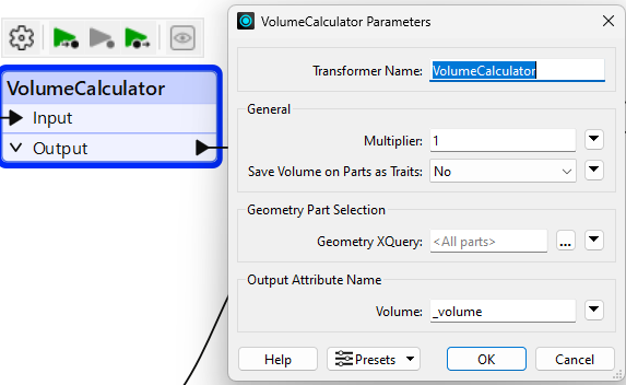
You can then use the VolumeCalculator transformer to obtain the volume of the solid.
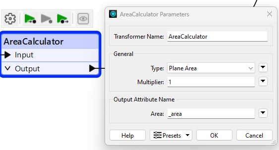
For calculating he surface are you can directly use the AreaCalculator transformer:
Calculate the A/V-Ratio from the obtained are and volume, you can merge the output features for the AreaCalculator and the VolumeCalculator using the FeatureMerger transformer:

To calculate the A/V-Ratio, you can use the AttributeManager transformer. Add a new attribute and set its value by using hte arithmetic editor.

Submission
Once you are done, please submit the following as a single zip file.
The FME Workbench file
The final CityGML Model of the Buildings, StreetSpaces and landuse along with textures attached in Task 3
The 3DPDF file.