Exercise 07: Automatic XML Schema from UML using ShapeChange
In this exercise you will use the UML model created in Exercise 02 and automatically derive an XML Schema from it using ShapeChange
Exercise Task
Preparation of the UML model
Note
Please make sure to read the tutorial and update all the necessary elements in your UML Diagram. The UML Model must have an application schema and classes must have stereotypes for this to work.
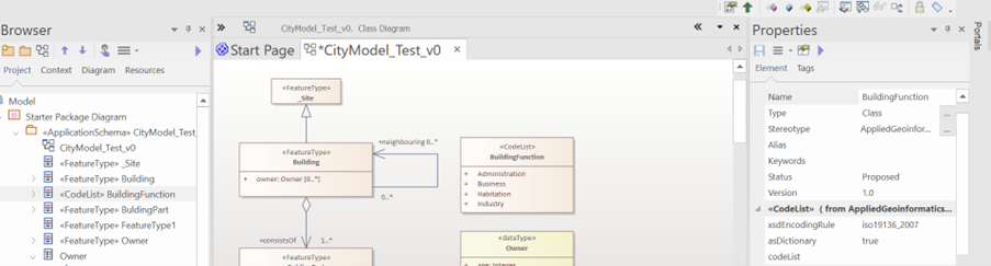
Defining the elements for the stereotype «ApplicationSchema»
The first task is to create/check your UML Model (as explained in Exercise 02: UML Modelling in Enterprise Architect) and make sure you have everything you need. Check ShapeChange under the sub-heading ‘Stereotypes to be used in the model’. As mentioned you also need to adapt the names of the xsdDocument, targetNamespace, xmlns and version.
For this, Click on the <<Application Schema>> in the Project Browser. The corresponding properties are then visible on the property Browser.

Make sure that…
#These details are added
 targetNamespace: www.gis.bv.tum.de/cm
 xmlns: cm.
 version: 1.0.
 xsdDocument: *DocumentName.xsd* #define your own document name.
Generation of CodeLists
If you want the CodeList to be generated. Click on the CodeList and open its properties. In the properties, change the value of asDictionary to ‘true’ as shown below.
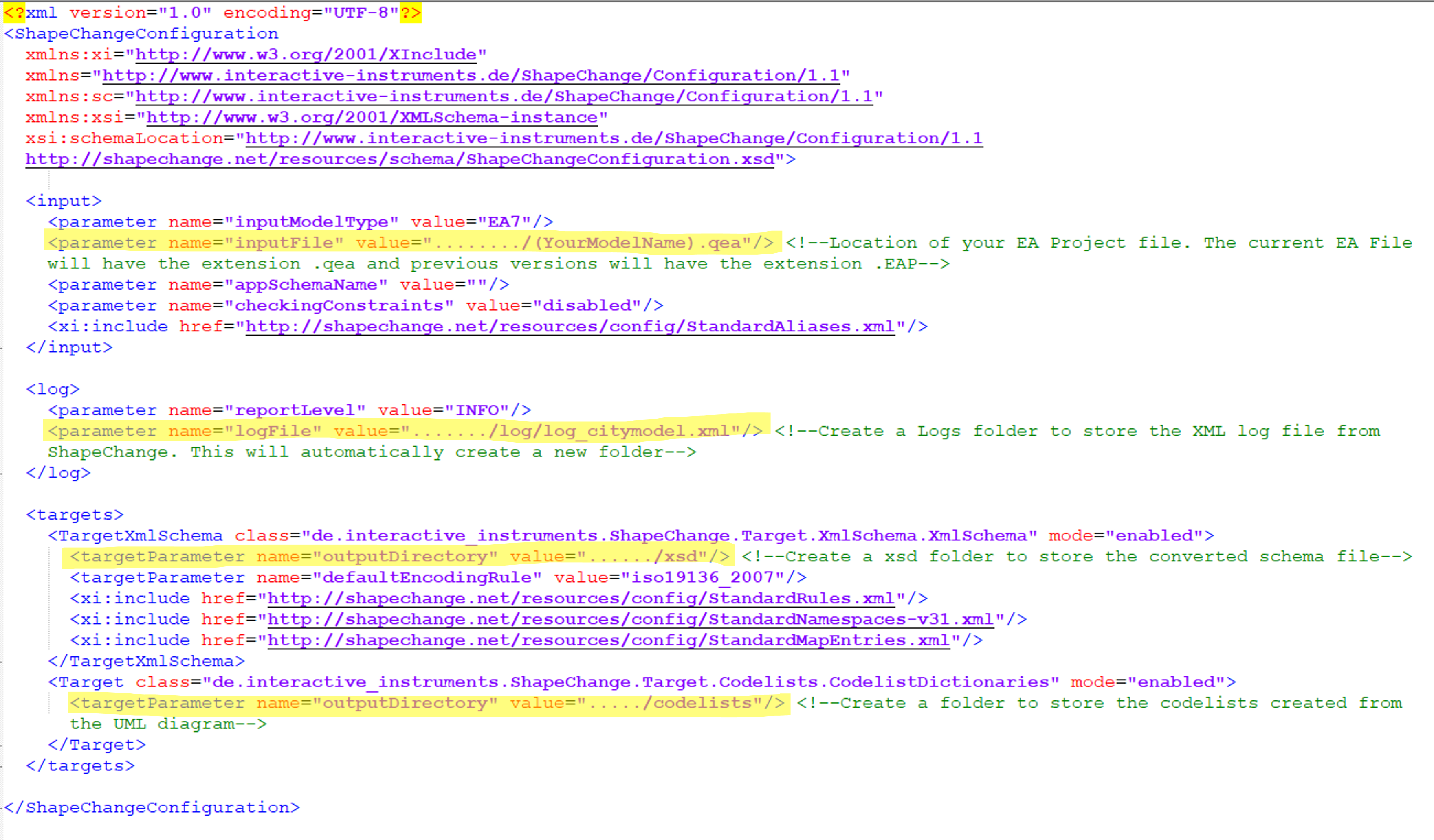
Editing the ShapeChange Configuration file.
You will find a ShapeChangeConfigurationFile here in the Data Repository
The following elements need to be adapted before you can run the application.
<input>: contains parameters and other information related to the input model. Location of the .qea Model
<log>: controls the logging of messages. Location of the destination logfile
<targets>: contains information on the targets of the transformation such as an XML Schema document and the CodeLists (if generated).
These are clearly marked in the following image.
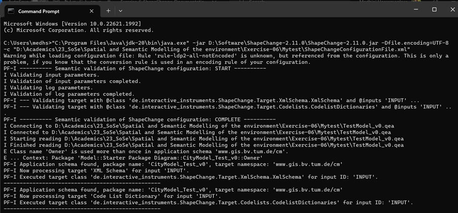
Running ShapeChange Application
ShapeChange uses a commandline interface for execution. The ShapeChange command has 3 components
Location of the Java .jdk file.
Location of the ShapeChange .jar file. This is given to you in the Data. You will need to unzip the ShapeChange-3.1.0_full.zip folder to find the .jar file.
Location of the ShapeChange Config file. This is the file you edited in the previous task.
#The command looks something like this.
"C:\Program Files\Java\jdk-20\bin\java.exe" -jar "Z:\Mytest\ShapeChange-3.1.0_full\ShapeChange-3.1.0.jar" -c "Z:\Mytest\ShapeChangeConfigurationFile.xml"
Find and adapt the locations of the files in the command before you run this.
On adapting and running it, if everything is done correctly, you should see the following screen on your commandline interface.
If successful, you will find 3 new folders i.e., codelists, xsd and log in your destination folder. If you open the xsd > INPUT, you will find the documentname.xsd file that you created. When you open it, it looks something like the one shown below.
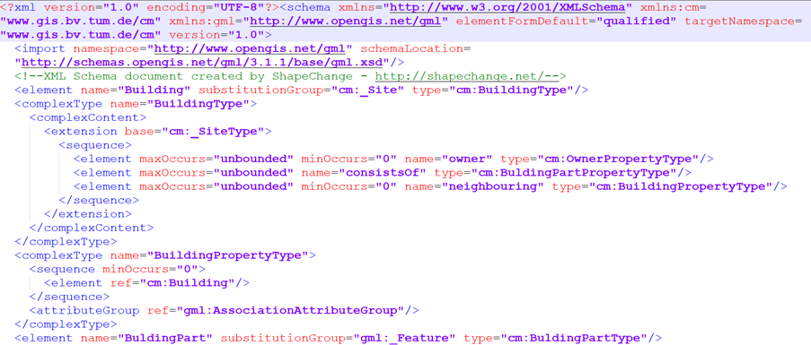
Note
Please note that the above screenshot is only a sample from some other model. The XSD will reflect the classes and the model you developed i.e., it will be about the Green space cadastre from Exercise 02.
You can relate this to the lecture of XML schema and encoding rules as taught by Prof. Kolbe. You have reached the end of the exercise and the end of all exercises for this semester! All the best for the exam!
Submission
There is no expected Submission for this exercise
This is only for your reference and checking.